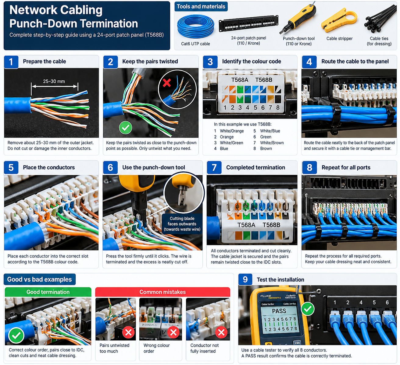
1. Understand the design before touching the hardware
Protect installed cable performance by planning routes, supports, pulling method, bend control, bundle management and service access before termination.
The practical rule is to separate what is physically possible from what is supported, what is supported from what is well designed, and what is well designed from what has actually been tested. Product names and connector shapes are useful clues, but they are not substitutes for the exact platform documentation.
Server Warehouse category links on this page identify relevant hardware families. Compatibility with a specific server, switch, storage platform, UPS, camera or cabling system must still be verified against the exact model and application.
2. Technical principles that matter
The pathway is part of the installation quality
A perfect termination cannot undo cable crushed in a tray, kinked around a corner or damaged during pulling.
Manufacturer limits matter
Maximum pulling tension and minimum bend radius vary by cable construction. Use the actual cable datasheet rather than a universal number.
Support spacing and pathway fill affect handling
Overfilled conduit or overloaded supports increase pulling stress and make future changes difficult.
Bundles need control without crushing
Hook-and-loop management is often preferable where repeated moves and changes are expected. Any tie method must avoid deforming the cable.
Power separation and EMI require site-aware design
Follow applicable standards, regulations and manufacturer guidance for parallel runs and crossings.
3. Field workflow
Use a repeatable process so that the result can be explained and handed over to another technician. Record the starting state before changing anything.
- Survey the complete route and identify sharp bends, penetrations and access points.
- Check cable datasheet for pulling/bend limits.
- Prepare supports and pathway before the pull.
- Use a controlled pull with communication between feed and pull ends.
- Inspect cable after pulling before termination.
- Dress, label and support the final route without crushing or excessive tension.
Where the manufacturer supplies a model-specific installation, population, compatibility or service procedure, that procedure takes priority over a generic field rule. The purpose of this workflow is to make sure the correct documentation is used at the correct point.
4. Worked field scenario
A bundle is pulled successfully but several links later fail return loss. Inspection finds a tight 90-degree bend around a tray edge and heavily cinched ties. The fault was created during pathway work, not at the RJ45 termination.
The important lesson is not the brand in the example. It is the reasoning chain: identify the requirement, trace the complete path, find the limiting or unsupported element, correct that element, and then prove the result with measurements or platform health evidence.
5. Fault-finding decision table
| What you see | Where to investigate next |
|---|---|
| Many links fail in the same physical area | Inspect the shared pathway for crushing, bends, heat or pulling damage. |
| Cable jacket is stretched or whitened | Treat it as evidence of excessive mechanical stress and evaluate replacement. |
| Links pass before ceiling work and fail later | Check whether other trades compressed or relocated the bundle. |
| Service loops become tangled masses | Redesign slack storage so loops are supported, identifiable and accessible. |
Change one variable at a time where practical. A fault that disappears after five simultaneous changes teaches very little and can return later because the real cause was never isolated.
6. What correct should look like
- Cable routes are supported and accessible
- No visible kinks/crush points
- Bends respect product guidance
- Bundles are labelled and not over-tightened
- Penetrations are correctly treated
- Certification confirms final installed performance
Acceptance is evidence, not confidence. Save configuration, test results, screenshots, logs, photographs, serial numbers or drawings appropriate to the job so that the next person can establish the known-good state.