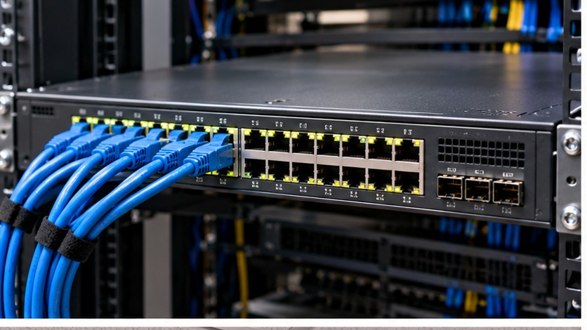
1. Understand the design before touching the hardware
Choose between direct-attach copper, active optical cable and separate optical transceivers by distance, compatibility, serviceability, power, bend handling and future changes.
The practical rule is to separate what is physically possible from what is supported, what is supported from what is well designed, and what is well designed from what has actually been tested. Product names and connector shapes are useful clues, but they are not substitutes for the exact platform documentation.
Server Warehouse category links on this page identify relevant hardware families. Compatibility with a specific server, switch, storage platform, UPS, camera or cabling system must still be verified against the exact model and application.
2. Technical principles that matter
DAC is a complete copper assembly
A DAC has integrated ends and no separate fibre patch lead. It is attractive for short in-rack or adjacent-rack links when both devices support the assembly.
AOC is also a fixed assembly
An active optical cable provides optical transport with integrated transceiver ends. It is lighter and reaches farther than passive copper options, but a damaged end usually means replacing the whole assembly.
Separate optics maximise modularity
Transceiver plus fibre lets you replace either component independently and can suit structured fibre pathways.
Compatibility is device-specific
A mechanically correct SFP-family connector does not prove firmware support. Check both endpoints.
Breakout and speed modes require special attention
Some high-speed ports can operate in breakout or alternate speeds, but only with supported cables/modules and switch configuration.
3. Field workflow
Use a repeatable process so that the result can be explained and handed over to another technician. Record the starting state before changing anything.
- Record both endpoint models and port types.
- Determine required speed and actual cable route length.
- Decide whether the link is fixed in-rack or part of structured cabling.
- Check vendor compatibility for DAC/AOC/optic options.
- Check bend path, cable bulk and service replacement needs.
- Install, label and verify DOM where available plus interface counters under load.
Where the manufacturer supplies a model-specific installation, population, compatibility or service procedure, that procedure takes priority over a generic field rule. The purpose of this workflow is to make sure the correct documentation is used at the correct point.
4. Worked field scenario
Two switches in the same rack need a 10GbE interconnect. A supported short DAC can be simpler than buying two optics and a patch lead. The same answer may be poor for a building backbone where structured fibre and replaceable optics provide better serviceability.
The important lesson is not the brand in the example. It is the reasoning chain: identify the requirement, trace the complete path, find the limiting or unsupported element, correct that element, and then prove the result with measurements or platform health evidence.
5. Fault-finding decision table
| What you see | Where to investigate next |
|---|---|
| Module is inserted but link stays down | Check endpoint support, speed mode, polarity where fibre is involved and whether the module is administratively enabled. |
| One vendor endpoint rejects the cable | Use a cable or optic supported by both devices rather than assuming coding is universal. |
| Link works until equipment is moved | Inspect bend radius, strain and connector seating. |
| Breakout links map to unexpected ports | Verify lane mapping and the switch's breakout configuration. |
Change one variable at a time where practical. A fault that disappears after five simultaneous changes teaches very little and can return later because the real cause was never isolated.
6. What correct should look like
- Both endpoints recognise the link component
- Expected speed is negotiated
- No CRC or physical-layer errors under load
- DOM values are recorded for optical links where available
- Cable route has safe bend and strain relief
- Link labels identify both endpoints
Acceptance is evidence, not confidence. Save configuration, test results, screenshots, logs, photographs, serial numbers or drawings appropriate to the job so that the next person can establish the known-good state.