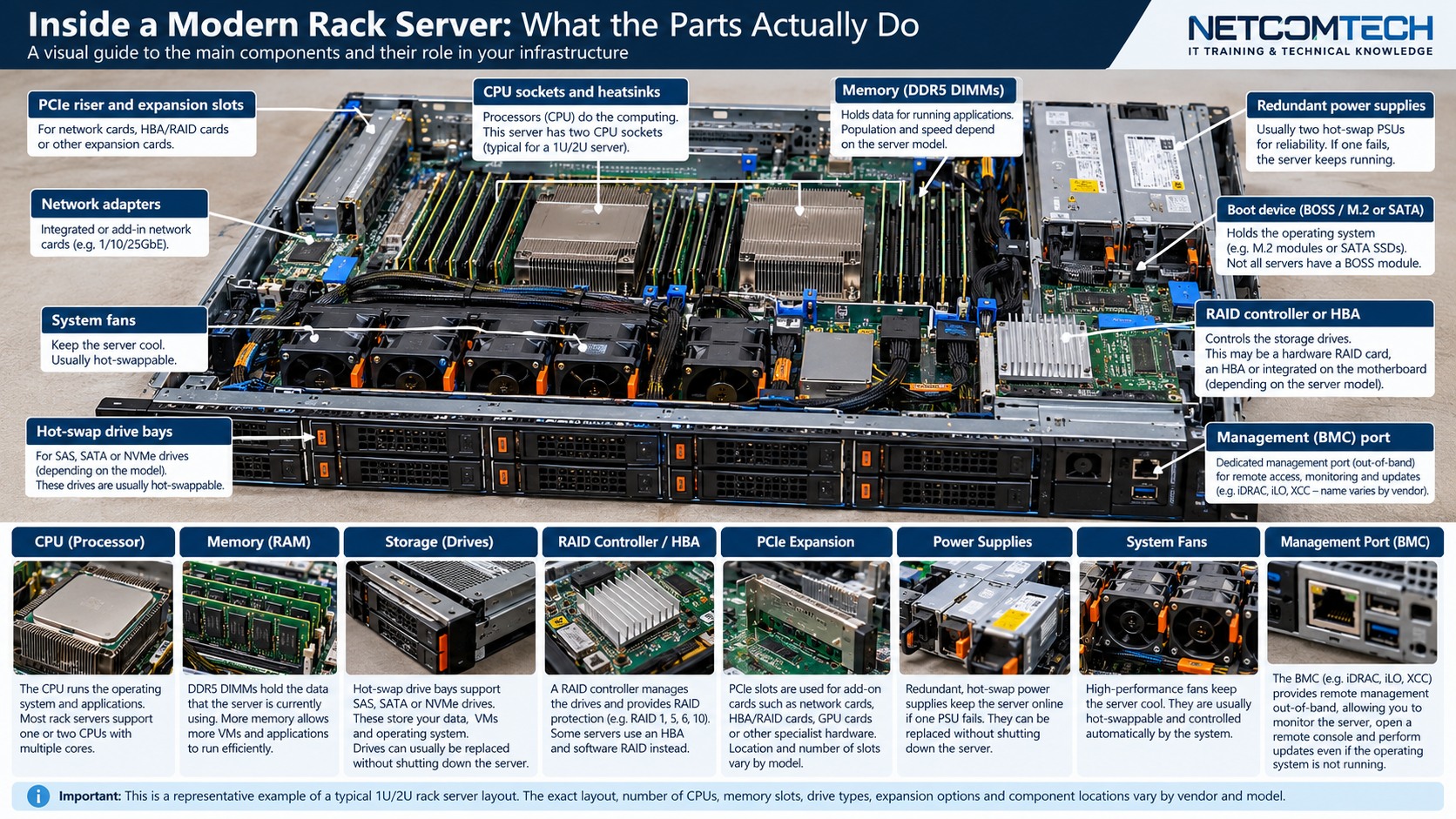
1. Understand the design before touching the hardware
Separate drive form factor from electrical interface so that an NVMe SSD, carrier and server backplane are treated as one compatibility chain.
The practical rule is to separate what is physically possible from what is supported, what is supported from what is well designed, and what is well designed from what has actually been tested. Product names and connector shapes are useful clues, but they are not substitutes for the exact platform documentation.
Server Warehouse category links on this page identify relevant hardware families. Compatibility with a specific server, switch, storage platform, UPS, camera or cabling system must still be verified against the exact model and application.
2. Technical principles that matter
A 2.5 inch drive shape does not identify the interface
SAS, SATA and NVMe devices can share a similar physical envelope. The server backplane, cabling and controller path determine what the bay can actually use.
NVMe reaches PCIe differently from SAS or SATA
NVMe storage is PCIe based. Depending on the server, lanes may reach front bays through a dedicated backplane, cables, retimers, switch devices or motherboard connections.
U.2 and U.3 are not a permission to mix blindly
Connector families and tri-mode backplanes can create confusing combinations. Compatibility must be checked at server and backplane level.
Carrier compatibility is mechanical and operational
The correct carrier must fit the chassis, present the drive properly to the backplane and support the platform's hot-plug and status indication design.
Boot support is a platform question
A server may detect an NVMe device but have different firmware requirements for booting from it, mirroring boot devices or exposing it through a RAID/tri-mode controller.
3. Field workflow
Use a repeatable process so that the result can be explained and handed over to another technician. Record the starting state before changing anything.
- Identify the exact chassis and front-bay/backplane option.
- Determine whether the target bay is SAS/SATA, NVMe, universal or tri-mode.
- Trace the path from bay to controller or PCIe root complex.
- Check carrier, drive thickness and supported capacity/form factor.
- Confirm firmware and boot/RAID mode requirements.
- Install one test device and verify enumeration, health, hot-plug indication and expected PCIe link before scaling the change.
Where the manufacturer supplies a model-specific installation, population, compatibility or service procedure, that procedure takes priority over a generic field rule. The purpose of this workflow is to make sure the correct documentation is used at the correct point.
4. Worked field scenario
A customer sees eight 2.5 inch front bays and assumes any eight 2.5 inch NVMe drives can be installed. The correct process identifies the fitted backplane option first. If only some bays are wired for NVMe, the storage design must respect those lane paths or the required backplane/controller kit must be included in the bill of materials.
The important lesson is not the brand in the example. It is the reasoning chain: identify the requirement, trace the complete path, find the limiting or unsupported element, correct that element, and then prove the result with measurements or platform health evidence.
5. Fault-finding decision table
| What you see | Where to investigate next |
|---|---|
| Drive fits but is not detected | Check whether the bay is actually wired for the drive interface and whether the required controller/cable/backplane option exists. |
| NVMe drive negotiates unexpectedly low performance | Check PCIe generation, lane width, slot bifurcation, retimer/switch topology and firmware. |
| Hot-plug behaviour is inconsistent | Verify the platform supports hot-plug for that exact bay and device path rather than assuming all front bays are hot-plug capable. |
| Boot device appears in OS but not firmware boot list | Check platform boot support, UEFI mode and vendor-specific boot configuration. |
Change one variable at a time where practical. A fault that disappears after five simultaneous changes teaches very little and can return later because the real cause was never isolated.
6. What correct should look like
- Drive is visible in management controller and OS
- Correct PCIe generation/lane width is recorded where exposed
- No backplane/controller health alarms
- Hot-plug indicators behave as documented
- Boot configuration survives restart if the drive is boot media
- Carrier and labels identify bay and function
Acceptance is evidence, not confidence. Save configuration, test results, screenshots, logs, photographs, serial numbers or drawings appropriate to the job so that the next person can establish the known-good state.