Workshop outcome
This chapter is intended to move beyond product awareness. It should help you plan the work, select the correct hardware class, execute or supervise the change, test the result and produce useful handover evidence.
DEEP TECHNICALFIELD WORKFLOWACCEPTANCE1. Understand what is shielded
Cable constructions can shield the overall cable, individual pairs or both. The component designation and manufacturer documentation define the construction.
2. Keep the component chain compatible
Shielded cable normally needs compatible shielded jacks, panels and patch cords if screen continuity is part of the design. Mixing unshielded components can break that path.
3. Terminate the screen as designed
Follow the exact jack/panel procedure for foil, braid and drain wire. Do not improvise by twisting a drain wire around unrelated metalwork.
4. Bonding is a building-system issue
Telecommunications bonding and earthing must follow the applicable site electrical/telecommunications design. Do not create ad-hoc earth connections because a rack happens to be nearby.
5. Avoid damaging the foil or braid
Strip only as required by the component instruction. Preserve the screen and pair geometry into the termination.
6. Check continuity where required
Use the appropriate tester/method for the system and project requirement. A basic wiremap that passes eight conductors does not necessarily prove screen continuity.
7. Troubleshoot systematically
If shield continuity is missing, inspect patch cords, jack contact, panel bonding and any unshielded transition point. Do not assume the cable itself is at fault.
8. Document the design
Record cable type, shield construction, panel/jack type, bonding points and test method. Future technicians need to know whether the screen path was intentional.
Worked field scenario
Shielded cable is installed to shielded jacks, but unshielded patch cords are later used at the rack. If the design depends on continuous screening, that component change breaks the intended path. The as-built documentation should make the screen chain visible.
Do not proceed from a product label alone. Convert the requirement into measurable compatibility, capacity, installation and acceptance checks.
Procurement questions before ordering
The ordering stage is where many field problems are created. Capture the following before selecting the exact product:
- Cable category and construction
- Permanent-link/channel requirement
- Compatible jack/panel/plug family
- Pathway and environmental conditions
- Required certification limit and test deliverables
Where a manufacturer compatibility list, rail matrix, supported-optics table or battery cartridge reference exists, record the exact source used for the decision. That gives the later installer evidence rather than a verbal assumption.
Fault-finding decision path
Read the tester parameter that failed before reterminating anything. Wiremap, NEXT, return loss, resistance, length and alien-crosstalk failures point toward different fault classes. Inspect the near termination, far termination and cable route with the failure signature in mind.
Keep a simple change log while troubleshooting: observation, action, result. If a change does not alter the symptom, put the system back unless there is a documented reason to retain it. This prevents troubleshooting from becoming an uncontrolled configuration drift.
Common mistakes that create repeat faults
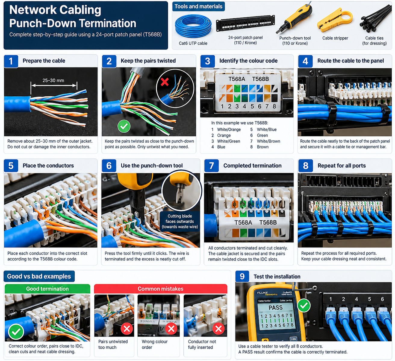
Do not untwist pairs farther than the component procedure requires. Do not crush bundles with tight ties. Do not mix plug/jack constructions by assumption, and do not call a link certified because a continuity tester shows eight conductors connected.
A technically successful installation can still be a poor operational result if the next technician cannot identify what was installed, why it was selected, or how it was tested. Serviceability is part of infrastructure quality.
Acceptance and handover evidence
Every link should have a stable identifier that matches panel, outlet and test record. Save certification files, not only printed PASS labels. Record repairs and retests so the handover package represents the final installed state.
Use filenames, labels and port/bay identifiers that match the physical installation. Handover evidence should let someone who was not present at the installation verify the final state and repeat the important tests later.
RELATED HARDWARE
Apply the lesson to Server Warehouse
These are educational category relationships. Always verify exact model compatibility, firmware, electrical limits, supported media and manufacturer requirements before ordering.
Technical references
Manufacturer documentation and the project specification remain authoritative for model-specific limits, procedures and safety requirements.