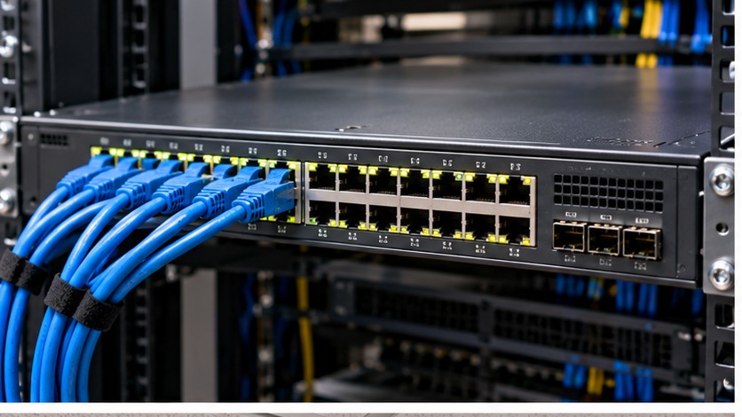
1. Understand the design before touching the hardware
Diagnose VLAN failures by following the frame path from endpoint access port through trunks, allowed VLANs, spanning tree and Layer 3 gateway rather than changing random switch settings.
The practical rule is to separate what is physically possible from what is supported, what is supported from what is well designed, and what is well designed from what has actually been tested. Product names and connector shapes are useful clues, but they are not substitutes for the exact platform documentation.
Server Warehouse category links on this page identify relevant hardware families. Compatibility with a specific server, switch, storage platform, UPS, camera or cabling system must still be verified against the exact model and application.
2. Technical principles that matter
Start at the endpoint VLAN
Confirm the access port is in the intended VLAN and that the endpoint has the correct IP configuration.
Then follow every trunk
The VLAN must exist and be permitted across each trunk in the path. One missing allowed-VLAN entry can isolate only part of a network.
Native VLAN assumptions cause confusion
Tagged and untagged behaviour must match at both ends. A mismatch can create leaks or unexpected connectivity.
Spanning tree can intentionally block a path
A trunk that is physically up is not proof that every VLAN is forwarding across it.
Layer 2 success does not prove routing
Once same-VLAN connectivity works, inter-VLAN failures move the investigation to SVIs, gateway addresses, routing and firewall/ACL policy.
3. Field workflow
Use a repeatable process so that the result can be explained and handed over to another technician. Record the starting state before changing anything.
- Record source and destination IP, VLAN and switch ports.
- Verify endpoint access VLAN and link state.
- Check VLAN existence on each switch in the path.
- Inspect trunk mode, allowed VLANs and native VLAN at both ends.
- Check spanning-tree state for the affected VLAN.
- Only after Layer 2 is proven, test gateway, routing, ACL and firewall policy.
Where the manufacturer supplies a model-specific installation, population, compatibility or service procedure, that procedure takes priority over a generic field rule. The purpose of this workflow is to make sure the correct documentation is used at the correct point.
4. Worked field scenario
Users in VLAN 30 work on one floor but not another. Both uplinks are physically up. Comparing trunk configuration shows VLAN 30 was never added to one intermediate allowed list. The fault is solved without touching DHCP, DNS or endpoint devices.
The important lesson is not the brand in the example. It is the reasoning chain: identify the requirement, trace the complete path, find the limiting or unsupported element, correct that element, and then prove the result with measurements or platform health evidence.
5. Fault-finding decision table
| What you see | Where to investigate next |
|---|---|
| Endpoint gets no DHCP address | First confirm access VLAN and trunk carriage before blaming the DHCP server. |
| Same VLAN works locally but not across switches | Focus on trunk allowed VLANs, VLAN existence and spanning tree. |
| Inter-VLAN ping fails but same-VLAN works | Move to gateway/SVI, routing and security policy. |
| Traffic appears in the wrong VLAN | Check access mode, voice VLAN settings, native VLAN and accidental trunking. |
Change one variable at a time where practical. A fault that disappears after five simultaneous changes teaches very little and can return later because the real cause was never isolated.
6. What correct should look like
- Access ports match design
- Trunks agree at both ends
- Allowed VLAN list is documented
- Spanning-tree state is understood
- Gateway reachability is tested
- Configuration backup and port map are updated
Acceptance is evidence, not confidence. Save configuration, test results, screenshots, logs, photographs, serial numbers or drawings appropriate to the job so that the next person can establish the known-good state.