Workshop outcome
This chapter is intended to move beyond product awareness. It should help you plan the work, select the correct hardware class, execute or supervise the change, test the result and produce useful handover evidence.
DEEP TECHNICALFIELD WORKFLOWACCEPTANCE1. OLTS and OTDR answer different questions
An OLTS measures end-to-end insertion loss. An OTDR characterises events along the fibre and can help locate connectors, splices, bends and faults. One is not simply a better version of the other.
2. Follow the project test requirement
Fluke notes that if Tier 2/extended OTDR testing is specified, it is required in addition to insertion-loss testing. The project specification determines acceptance.
3. Clean before reference and test
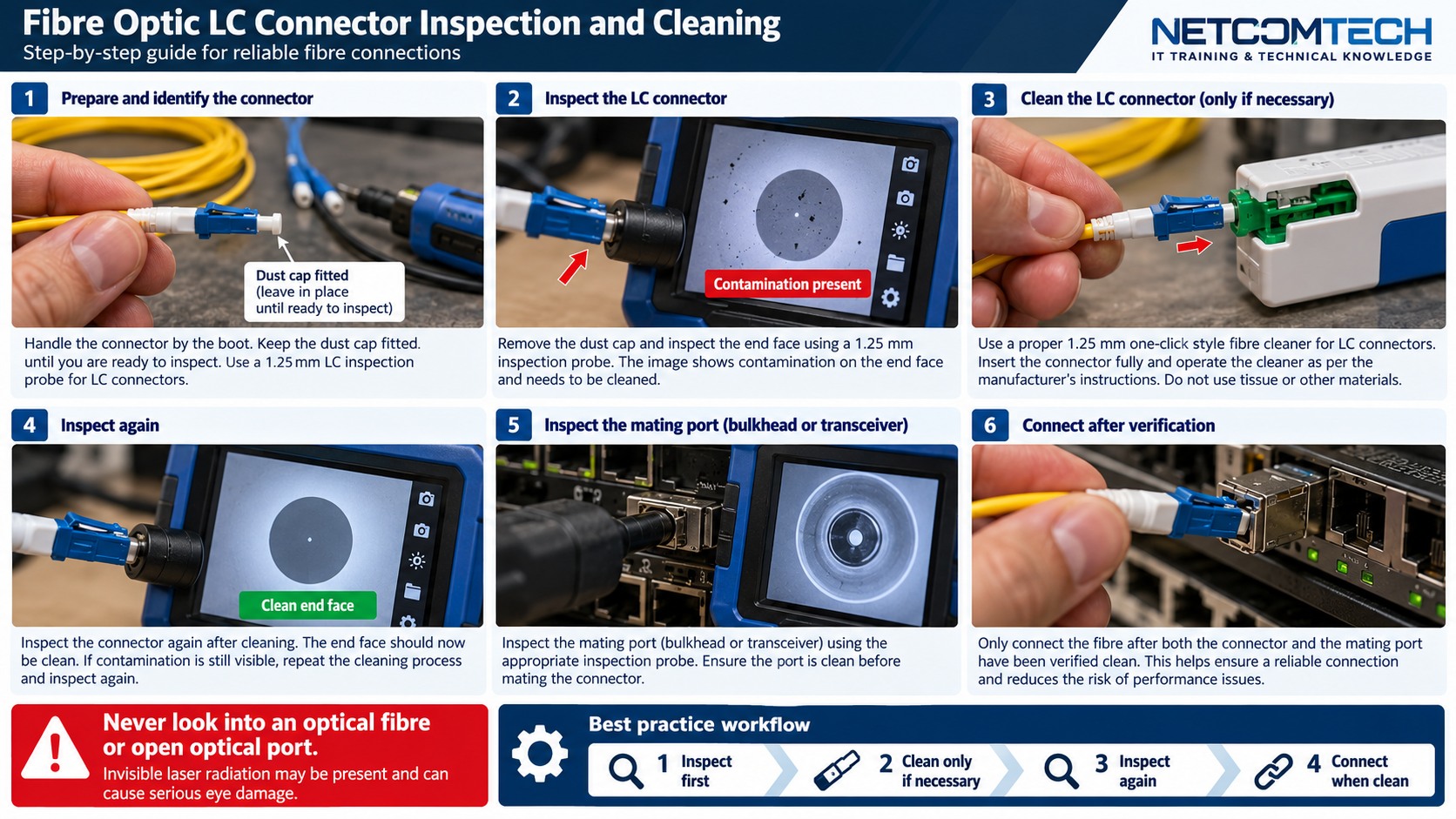
Dirty test cords corrupt the reference and the link measurement. Inspect and clean test equipment ports and reference cords before establishing the reference.
4. Set the reference correctly
Use the test method required by the standard/project and do not disconnect reference connections that the procedure says must remain in place.
5. OLTS acceptance
Test the required wavelengths and compare measured insertion loss to the project limit. Save results against the exact fibre ID.
6. OTDR launch and receive fibres
Launch and receive fibres allow the instrument to characterise the near-end and far-end connectors. Use appropriate fibre type and length for the link/tester.
7. Interpret events, not just PASS/FAIL
Review event loss, reflectance, distance and unexpected events. A trace can reveal workmanship issues even when total loss is within budget.
8. Test both directions where required
Bidirectional OTDR testing can improve event-loss characterisation because apparent splice loss can be affected by backscatter differences.
9. Handover package
Provide OLTS results, OTDR traces where required, fibre IDs, wavelengths, test method, reference-cord details, tester calibration status and repaired-fault notes.
Worked field scenario
A fibre passes OTDR event limits but fails end-to-end insertion loss. The tests answer different questions. Use the OLTS result as the end-to-end acceptance evidence where specified, then use the OTDR to locate where unexpected loss is occurring.
Do not proceed from a product label alone. Convert the requirement into measurable compatibility, capacity, installation and acceptance checks.
Procurement questions before ordering
The ordering stage is where many field problems are created. Capture the following before selecting the exact product:
- OS2/OM fibre type and strand count
- Connector and polish at every interface
- Optic wavelength and supported reach
- Expected loss budget and test method
- Patch-panel, splice and polarity plan
Where a manufacturer compatibility list, rail matrix, supported-optics table or battery cartridge reference exists, record the exact source used for the decision. That gives the later installer evidence rather than a verbal assumption.
Fault-finding decision path
Inspect and clean before deeper troubleshooting. Then verify optic recognition, Tx/Rx pairing and polarity. Use DOM as live equipment evidence, OLTS for end-to-end insertion loss and OTDR when event location or characterisation is needed. Keep the design loss budget beside the measurements.
Keep a simple change log while troubleshooting: observation, action, result. If a change does not alter the symptom, put the system back unless there is a documented reason to retain it. This prevents troubleshooting from becoming an uncontrolled configuration drift.
Common mistakes that create repeat faults
Do not look into live fibre. Do not mate APC and UPC interfaces. Do not assume a dust cap means clean, and do not use an OTDR trace alone as a substitute for insertion-loss acceptance when the project requires OLTS testing.
A technically successful installation can still be a poor operational result if the next technician cannot identify what was installed, why it was selected, or how it was tested. Serviceability is part of infrastructure quality.
Acceptance and handover evidence
Provide fibre IDs, route, fibre type, connector/polish, splice locations, optic types and measured results. Store original OLTS/OTDR result files where possible so future technicians can compare traces and losses rather than relying on screenshots.
Use filenames, labels and port/bay identifiers that match the physical installation. Handover evidence should let someone who was not present at the installation verify the final state and repeat the important tests later.
RELATED HARDWARE
Apply the lesson to Server Warehouse
These are educational category relationships. Always verify exact model compatibility, firmware, electrical limits, supported media and manufacturer requirements before ordering.
Technical references
Manufacturer documentation and the project specification remain authoritative for model-specific limits, procedures and safety requirements.