Why this chapter exists
A dirty connector can take a high-capacity uplink down while leaving the cable itself perfectly intact.
See the physical work before reading the details
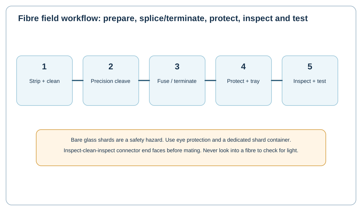
Original Netcomtech training illustration. Product-specific termination geometry varies, so use the component manufacturer's instruction sheet on site.
16.1 Set up a controlled work area
Use eye protection, a dark or high-contrast work surface where helpful, dedicated fibre stripping/cleaving tools and a rigid glass-shard container. Never leave bare fibre fragments on the bench.
16.2 Strip and clean
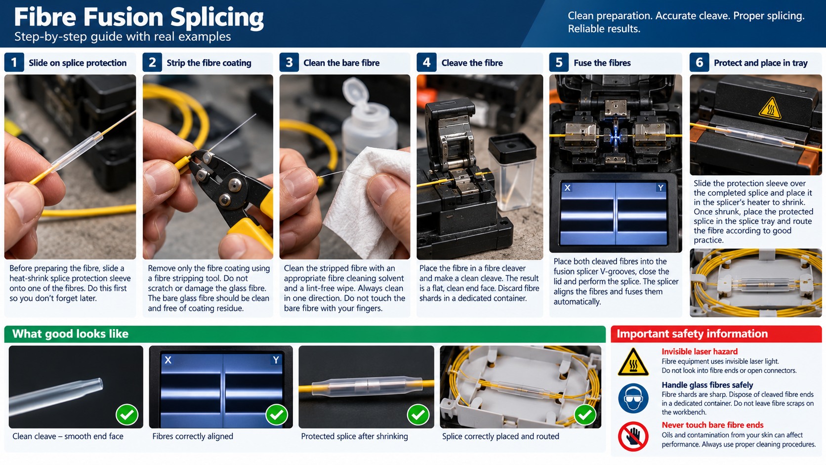
Remove the jacket/strength members and buffer/coating using the cable and splice-system instructions. Clean the bare fibre with the approved method before cleaving.
16.3 Precision cleave
The fusion splicer expects a clean, controlled end face. Use a proper cleaver and keep its blade/holder clean. Do not touch the prepared glass.
16.4 Fuse and inspect the process
Load fibres into the splicer as instructed, run alignment/fusion and inspect the machine's process feedback. The splicer's estimated loss is process information, not a substitute for field optical testing.
16.5 Protect and tray
Center the splice sleeve over the bare splice, shrink it fully, then route the protected fibre into the tray without violating bend radius or creating pressure points.
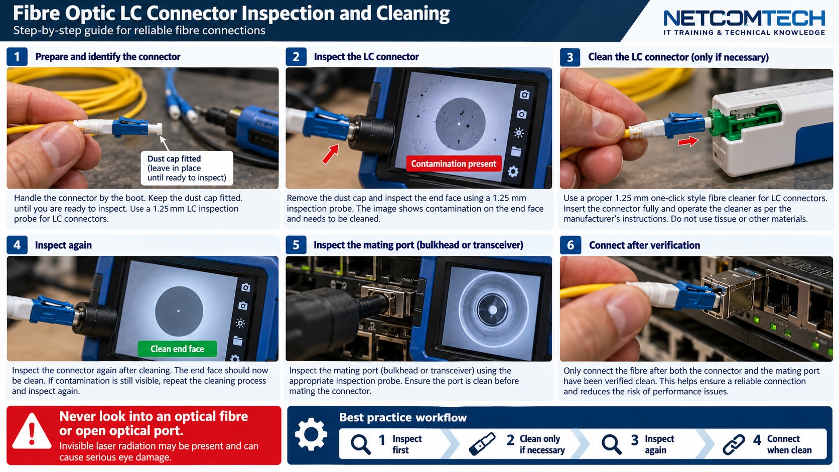
16.6 Inspect-clean-inspect connectors
Before mating connectors, inspect the end face, clean if needed and inspect again. Never look into a fibre or transceiver to check whether light is present.
16.7 Test the completed link
Use OLTS for end-to-end insertion loss when required and OTDR for event location/characterization. Save results with the same cable ID used on the patch panel and drawings.
Workshop exercise
Build a sample of this installation method on a training bench. Photograph the preparation before termination, the finished termination and the test result. Explain what would cause you to reject your own work.
Acceptance checklist
- The component matches the cable construction and category.
- The manufacturer's installation method was followed.
- No conductor, jacket, screen or fibre damage is visible.
- Pair twist, bend radius and strain relief are preserved.
- The correct test model and limit were used.
- The cable ID matches the drawing and test report.
Technical references
Manufacturer instructions and the project standard always override generic training examples.