Why this chapter exists
A neat cable route that runs beside noisy electrical equipment can create intermittent errors that are difficult to diagnose later.
See the physical work before reading the details
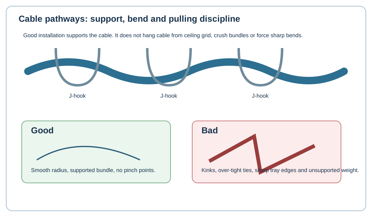
Original Netcomtech training illustration. Product-specific termination geometry varies, so use the component manufacturer's instruction sheet on site.
9.1 Do not use one universal distance
Required separation depends on cable type, power circuit, containment, shielding and the standards or local electrical rules that apply to the project. Avoid teaching one magic distance for every installation.
9.2 Identify the real interference sources
Large motors, variable-frequency drives, transformers, fluorescent/LED power gear and high-current feeders deserve attention. Ordinary office circuits in compliant containment are a different risk.
9.3 Cross rather than parallel where practical
When data and power must pass, a short crossing is generally easier to manage than a long parallel run. Follow the project design and local code requirements.
9.4 Shielding is not permission for bad routing
Screened cable can improve noise immunity, but it still needs correct connector termination and bonding. Do not route shielded cable through avoidable electrical hazards simply because it is shielded.
Workshop exercise
Build a sample of this installation method on a training bench. Photograph the preparation before termination, the finished termination and the test result. Explain what would cause you to reject your own work.
Acceptance checklist
- The component matches the cable construction and category.
- The manufacturer's installation method was followed.
- No conductor, jacket, screen or fibre damage is visible.
- Pair twist, bend radius and strain relief are preserved.
- The correct test model and limit were used.
- The cable ID matches the drawing and test report.
Technical references
Manufacturer instructions and the project standard always override generic training examples.