Why this chapter exists
In electrically noisy or high-performance environments, shielding can improve immunity, but incorrect termination can remove the benefit and create confusing faults.
See the physical work before reading the details
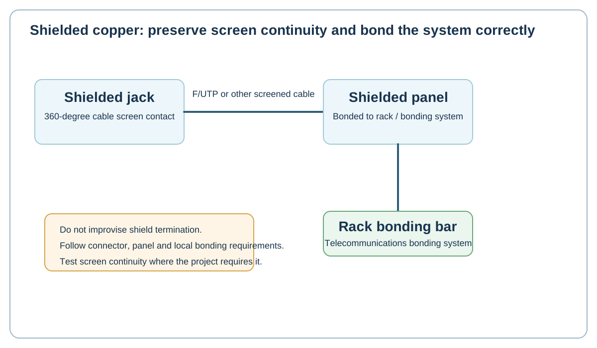
Original Netcomtech training illustration. Product-specific termination geometry varies, so use the component manufacturer's instruction sheet on site.
11.1 Know the cable notation
Terms such as F/UTP and U/FTP describe the overall screen and pair shielding construction. Record the exact cable system rather than calling everything STP.
11.2 Maintain 360-degree shield continuity
Use screened jacks, plugs, patch cords and patch panels that match the cable system. The manufacturer's termination method determines how foil/braid/drain elements are prepared.
11.3 Bond the telecommunications system
Leviton's application guidance describes shielded panel bonding into a telecommunications bonding system and notes the relevant TIA-607-D context. Local electrical and building requirements also apply.
Do not invent an earth connection at the work-area jack unless the system design calls for it.
11.4 Test screen integrity where required
Modern certification testers can verify shield continuity and, on some platforms, locate shield faults. A simple continuity path may be misleading if current finds another grounding path.
Workshop exercise
Build a sample of this installation method on a training bench. Photograph the preparation before termination, the finished termination and the test result. Explain what would cause you to reject your own work.
Acceptance checklist
- The component matches the cable construction and category.
- The manufacturer's installation method was followed.
- No conductor, jacket, screen or fibre damage is visible.
- Pair twist, bend radius and strain relief are preserved.
- The correct test model and limit were used.
- The cable ID matches the drawing and test report.
Technical references
Manufacturer instructions and the project standard always override generic training examples.